This is an adaptation to the Taig of a Unimat 3 threading attachment described by J. H. Frost in the March/April 1994 issue of the Model Engineers' Workshop. The approach resembles a woodworking lathe duplicating attachment in that it simply copies any thread pitch for which you already have a sample. Because this eliminates the need for change gears and a leadscrew, it makes threading pretty simple and inexpensive.
To anyone doubting its effectiveness, just have a look at the work of John Bentley who used a similar technique for years in craftsmanship of the highest quality.
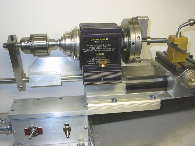
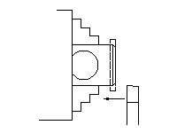
A three-jaw chuck mounted outboard on the headstock spindle carries a threaded leader with the pitch to be copied. Riding on the leader is a follower nut which is connected to a drive rod. The drive rod runs through a guide block to a connection on the lathe carriage. As the lathe spindle turns, the lead of the follower nut on the leader is duplicated in the movement of the lathe carriage and its cutter.
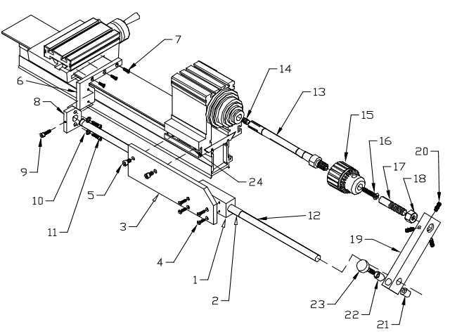
| Part | Quantity | Description |
|---|---|---|
| 1 | 1 | Drive Rod Guide Block |
| 2 | 1 | Drive Rod Guide Block Bushing |
| 3 | 1 | Drive Rod Guide Block Hanger |
| 4 | 4 | 4-40 x 7/16" Flat Head Machine Screw |
| 5 | 2 | 8-32 x 1/2" Socket Head Cap Screw |
| 6 | 1 | Carriage Plate |
| 7 | 3 | 3-48 x 3/8" Flat Head Machine Screw |
| 8 | 1 | Drive Rod Plate |
| 9 | 1 | 6-32 x 1/2" Socket Head Cap Screw |
| 10 | 2 | #4 Washer (5/16"OD, 1/8"ID) |
| 11 | 2 | 4-40 x 1/2" Socket Head Cap Screw |
| 12 | 1 | Drive Rod |
| 13 | 1 | Chuck Arbor |
| 14 | 1 | 1/4-20 x 3/8" Socket Head Set Screw |
| 15 | 1 | 3/8" Drill Chuck - Jacobs 22BA or equivalent |
| 16 | 1 | Chuck Retaining Screw |
| 17 | 1 | Thread Leader (Any bolt, screw or threaded rod) |
| 18 | 1 | Thread Follower (Hex nut to match leader) |
| 19 | 1 | Drive Link |
| 20 | 3 | 10-32 x 1/2" Socket Head Set Screw |
| 21 | 1 | Rod Clamping Nut |
| 22 | 1 | Rod Clamping Bushing |
| 23 | 1 | Rod Clamping Finger Screw |
| 24 | 2 | 8-32 T-nut (3/4" x 3/8" x 1/8") |
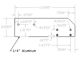
The dimensions shown are those I ended up with and will not necessarily suit all situations. Alignment of the drive rod is critical and depends on exactly how it is attached to the carriage. From this follows the design of the guide block and its hanger. Finally, the drive link depends on the precise distance of the rod from the arbor.
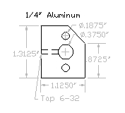
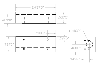 This is the part that determines how accurately the drive rod parallels the lathe bed. The hole must be as straight and true as possible. Here's one way to do it.
Cut the block a little oversize and true up all six sides in the four-jaw chuck. Remount for tailstock drilling and progressively drill out to 1/64" under the 13/32" final diameter. Finally, drill in 1/8" or so to start a 13/32" D-bit reamer and ream through at about half the previous drilling speed or less.
This will make the hole straight, but not necessarily true. If it's not true, remount in the four-jaw using a 13/32" transfer punch through the hole and suitable spacer blocks to align the hole with the chuck body. Reface each side of the block in this way to true it up around the hole.
Leave the mounting holes until after the guide block hanger is complete.
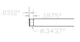
This is a 2 7/16" long piece of brass tubing available at any model aircraft or railroad store. It is 13/32"OD and 3/8"ID and makes an easily replaceable wear surface for the drive rod. Friction would probably secure it but I used a little 222MS Loctite to be sure.
The length of this part is calculated to bring support for the drive rod as close as possible to where the drive link clamps to it. This helps to neutralize the significant bending moment exerted on the rod by the drive link at start-up.
After shaping the hanger, drill the two #13 (.185) clearance holes for the 8-32 mounting screws. Clamp the guide block to the hanger in the proper position to drill the 4 joining screw holes. If you don't have jig boring facilities, consider this approach. Locate the clamped parts on the drill press, drill the pilot hole, then the clearance hole and then countersink, - all without moving the parts. If tapping, do that next in the same position. Then put in the screw before moving on to the next hole position.
When working with aluminum, every screw can be a self-tapping screw if the pilot hole is right. For 4-40, instead of the common #43 (.089) tapping pilot, try a #36 (.1065). A standard 4-40 SHCS will then thread right in with only modest torque and you'll never strip it out. This saves a lot of time and effort, especially in blind holes. The base on which my Taig is mounted was made this way and it's as solid as if it were welded.
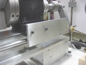
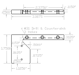 The design of this part was heavily influenced by the fact that my carriage had already been drilled and tapped on both sides to mount holders of bed wipers made from lengths of 1/8"-square leather boot lace. So this is really just a new wiper holder with an extension shaped to allow attachment of the drive rod.
To get a flat, perpendicular surface for the plate, it was necessary to mill a bit off the side of the carriage. The original casting surface irregularity doesn't matter for a bed wiper but does for this plate. Clearly, the carriage can't be milled in the Taig because it is an integral part of the milling attachment. I do light milling of this kind with an X-Y vise on the drill press. The stopped dado in the holder for the boot lace can be done either the same way or with the milling attachment.
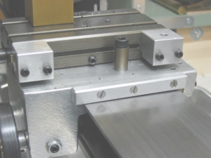
 This part is only provided to allow fine horizontal and vertical adjustment of the drive rod attachment to the carriage. First drill the 3/8" hole, drill and tap the 6-32 grub screw hole. Run the drive rod through the support block, secure it in the rod clamp with a 6-32 SHCS and use a toolmakers' clamp to secure it temporarily to the mounted carriage plate. Use the rack feed to move the carriage back and forth through its full range, shifting the rod clamp and/or the guide block hanger as needed to align for smooth movement. When it seems right, disassemble keeping the rod clamp and carriage plate still clamped together. Drill the 4-40 pilot and clearance holes and tap. Reassemble with the screws and washers. The 3/16" clearance holes should be ample for final adjustment.
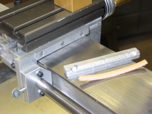
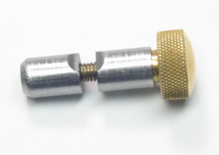
 This is just a suitable length of 3/8" drill rod. 18" is sufficient to allow threading at any point between centers on a Taig. The only machining is a groove at the end where the grub screw bears on the shaft.
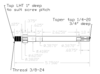
The length of the arbor brings the 1/4-20 set screw to just shy of the headstock taper so it's easy to reach with an Allen key. With a nice snug fit in the spindle, turning the set screw into the taper-tapped hole expands the two-way split end for a very tight fit. My spindle has been drilled out to 25/64" so the diameter shown will have to be adjusted for a stock spindle.
The outboard end is like a shoulder screw and it's the fit of the 1/8" shoulder and the squareness of the 5/8" base that determine the truth of the running chuck. The 3/8-24 thread just holds it firmly against these aligning surfaces. So making the thread with a common die works just fine.
During tapping the chuck is subject to a torque which tends to loosen it on the arbor. A left-hand thread retaining screw is a well proven solution used in all reversible drills. Any repair shop should have replacements on hand. The manufacturers seem to specify either M5 or 10-32 left hand thread pan head screws. Mine are all 10-32 but the screws available to you may differ so you should have one in hand before buying the LHT tap.
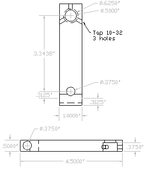
Make this part from a piece of 1/2" x 1" CRS. The actual length is determined by the distance from the rod to the chuck center line which will be obtained by scribing after it is attached to the drive rod. So be a little generous when cutting the initial blank.
The most unusual aspect of this part is the substituion of a split cotter for the more common pinch bolt method of locking things to shafts. Pinch bolts are problematic at the best of times but just about unworkable with a piece of 1" steel. The split cotter, however, is just outstanding. It takes only a very light touch to get a really solid lock.
The cotter and its housing really have to be made together and the making is not at all self-evident. At least, it wasn't to me. I learned about this remarkable device from The Machinist's Bedside Reader by Guy Lautard to whom I am most grateful for permission to reprint the following instructions.
Usually, the hole for the cotter is located and drilled, bored and/or reamed. Next, the cotter blank, which may take various forms, is stuffed into the hole, locked rigidly there, and the intersecting hole for the spindle drilled and bored or reamed. Finally, the cotter blank is removed, split, cleaned up, and the parts assembled.

The commonest way to secure a split cotter blank in its hole for cross machining, is to make the cotter as a flanged blank.
The cotter blank...
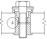
Then it is secured in its hole.
.... is clamped in place for
boring of the spindle hole ....
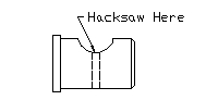
After machining out the spindle bore, the cotter blank will look like this. We put a hacksaw through the middle of the little notch, chuck each of the halves, and clean up the sawn face.
.... sawn in two ....
In the case of the flanged half, we first chuck it the other way around to face away the flange. Obviously, the space between the two halves of the cotter need be no more than that provided by the hacksaw cut, but it would be rather slovenly not to clean up the sawn face.
.... the flange removed,
and the ends faced ....
It goes without saying that the various sharp corners are chamfered ever so slightly so the final assembly is neat and clean.
.... whereupon it is completed
and installed....
Ed Note: In this particular case, I used a brass finger screw instead of a socket head cap screw. Actually, this is the original Taig tailstock ram clamping screw which was left over when I converted to ball handles. This provides all the purchase you need for a solid lock.
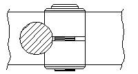
Once the link is connected to the drive rod, the rest of the machining is pretty straightforward. To locate the center for the leader/follower holes, put a little layout dye on the end of the link, chuck an accurately pointed object ( turned if necessary ) and scribe a rod-centered arc to intersect with a center-line on the link. This gives the hole centers and the rest is easy. Drill and tap the three set-screw holes at 120 degrees and you're done.
Turning threads on a lathe requires multiple passes and there must be some way to return the cutter for the next pass. The other attachments I'm aware of use one of two approaches: a handwheel to manually wind the carriage back or a kind of split-nut quick disconnect on the follower to allow the carriage rack feed to do the return. I elected to go with a motor reversing switch. Without any additional design complexity, you've got a stress-free way to go back at the same speed you went forward and no problem in picking up the thread for the next pass.
No threading attachment, including change gears and lead screw, is much good if the slowest speed available is the Taig's minimum 525rpm. If you can't achieve speeds of 100rpm or less, lathe threading is likely to be a pretty gut-wrenching experience.
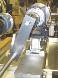
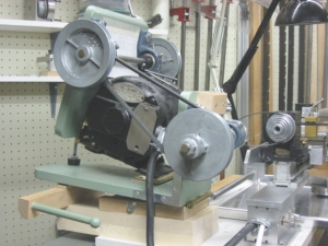
Just about everything out there on this subject seems to involve variable speed motors, DC or universal. My alternative is a system you might call "belt implemented back gearing".
The photo shows a prototype which I hope someday to remake in a more compact form. It's grotesque, but effective. The pulleys are 1 1/2" and 4 1/2" 4L pulleys available in any hardware store. The actual pitch diameters are 1 1/4" and 4 1/4" respectively so the reduction is theoretically 1:3.4. The motor drives the countershaft at a fixed reduction of 1725/3.4 or 507rpm. A quick-change belt allows the countershaft to drive the jackshaft at either 507 x 3.4 = 1725rpm or 507/3.4 = 149rpm. The jackshaft then drives the lathe with the standard Taig pulley set. This gives a "back belt" speed range of around 45rpm to 474rpm, complementing nicely the direct range of 525rpm to 5500rpm.
© 2006 Keith Brooke
![]()